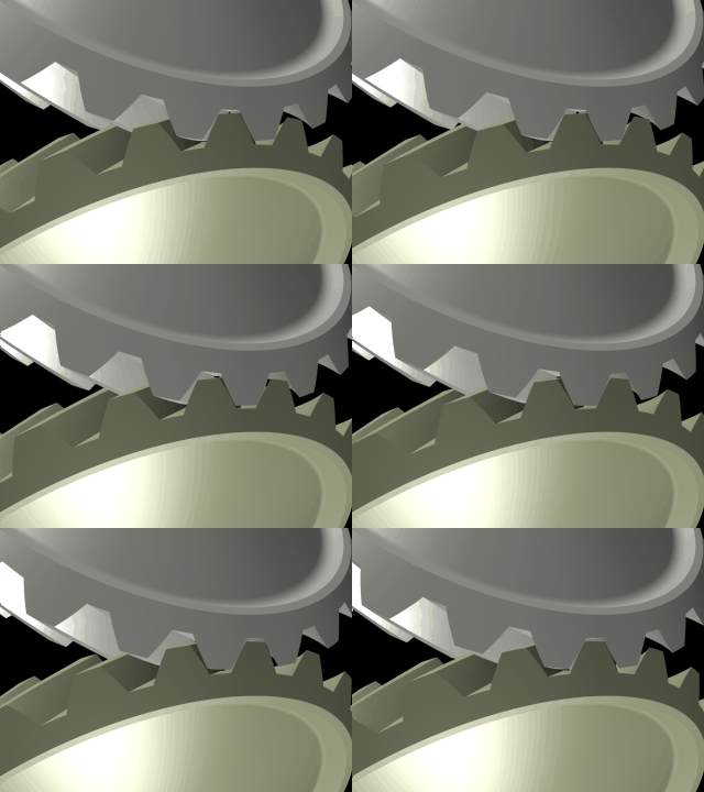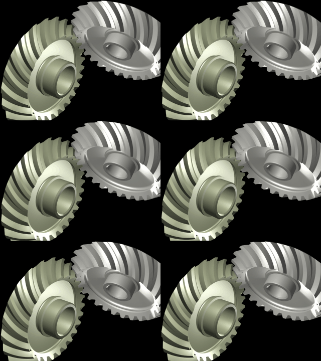


The digital models were created using DDS with geometrical accuracy of 0.00001 mm.
A new method of composite gear inspection.
The author proposes a new method of computerised composite gear inspection method that is applicable for all kinds of gears. The method is based on DDS and consists of two steps:
1. Digitizing the gear set.
2. Meshing digitized gears together or with a digital master gear in computer program.


The digital models were created using DDS with geometrical accuracy of 0.00001 mm.
The method allows significantly decrease the cost of tooth contact analyse (TCA) equipment. A simple 3D numerical controlled (CMM) measuring machine with appropriate software can replace an expensive single-flank contact inspection machine.
Examples of using the method for Spiral Bevel, Hypoid, Tapered face worm gear set, Worm, Globoid, Crown, and other gears are provided.
Single-flank inspection method is currently the most informative method of gear inspection. It provides the best information about the functionality of the gear mesh. Transmission error and bearing contact are the main data for determination of the gear performance. Single-flank contact inspection machines are mostly used for the final determination of the acceptance of the gear set. Individual measurements such as profile, run-out, lead or spacing is useful for controlling of the manufacturing process. Deviation in each of these individual parameters causes a transmission error. However for example deviation of the run-out may work against deviations on spacing so the transmission error caused by the run-out may be decreased by the transmission error caused by spacing error. It means that some gear sets with large individual deviations may be acceptable in a set. That is why composite inspection is so important in a large value of gear production. The quality of each individual gear can be decreased because it might be possible to find another low quality mating gear that makes an acceptable mesh in a set. The measuring against a master gear is another advanced way of using single-flank composite inspection machine. It makes it possible to utilize such of equipment for analyzing an individual gear. The cost of inspection may be low for high value of production. However the measuring method against a master gear requires a master gear. The output data in this case include the data from the measured gear and the error data from the master gear as well. Such of solution makes it questionable in using single flank composite inspection machines for high accuracy ground gears. Unfortunately single-flank inspection machines are expensive and not widely used in gear shops. Besides the cost these machines require manufacturing of precision tools for gear set-up. An average cost of composite inspection for one gear set can be up to 300% higher then inspection by individual parameters. Presently the most common gear inspection machine is a 3D numerical controlled measuring machine (CMM). ZEIZZ, HOEFLER and M&M are well known in the gear industry. These machines are mostly universal. They can be used in inspection of other things than gear teeth. It makes them attractive for investments. This article attempts to describe the author experience of using general propose ZEIZZ CMM for composite single gear tooth flank inspection. The method was developed at automotive industry for tapered and flat face worm gear drive. A single flank composite checker was simulated in the computer memory. Special software was written for analysing the data from the CMM. Computer program created a 3D copy of gears on the hard drive of the real gears and put them in mesh. Digital models of real gears with all of manufacturing errors were in the virtual rotation inside a PC. The output is a contact bearing and transmission error for the real gear drive.
Single-flank composite inspection machine can be successfully replaced by an average CMM with the gear mesh software. CMM does not need an accurate tooling for alignment of the gears. The software takes care of all alignments. It also does not need a master gear. The master gear can be created within a second by the software. The computer program has so many benefits against real metal machines. I personally like to analyse the alignment of gears on my notebook during my oversee flights. It feels like I have a full storage of gears in my packet so I can pick them up in 3D and mesh them together in a minute. Computer program provides some futures that are not possible on real machines. The program can show not only the composite contact pattern but it also shows how this pattern was generated. The program shows an area of contact for two mating surfaces of the gear teeth. It shows the main axis of the contact ellipse. Unfortunately it is complicated to show animations in the magazine article but animation futures are the most advanced benefit of the computer program against the machine. The program can show the mesh and the contact in motion. It shows where the contact starts and where it disappears. This motion computer gear TCA was used by author the first time during development of parabolic toot profile modifications on helicopter transmissions in 1987-1990. Computer program was written for analysing of premanufacturing parabolic type of transmission error on spur and helical gears. The parabolic curvature of transmission error was achieved by using invented by Boris V. Zakoldaev (USSR #1593354 1987) a parabolic shape of tooth modification. The program was applied for involute gears and for not involute gears such as Novikov, Wildhaver and IP as well. Simulations of the transmission error and noise for these gears were done.
The other unique benefit of the program is transmission error for each individual tooth. There are many tricks for getting a transmission error for just one pare of teeth on the real machine. It can be a tape on the tooth flank or it can be all other teeth removed from the gear. The way exists but it is newer used because it is too complicated. That is why the machine does not give much of inspection information on high contact ratio gear drives. A tapered and flat face worm gear drive is an example. With contact ratio more than 2 it makes a single-flank analyser useless as a manufacturing inspection tool. The software gives transmission error for each individual tooth as well as for a gear train. The program uses the readings from CMM machine. CMM has to provide as many coordinats as possible so the program can build an accurate 3D model. The base data for the program are following:
- base surfaces such as bearing shoulders and diameters
- mapping of the tooth surface.
The most accurate simulation will be done if all of the teeth on the gears are measured. This is a disadvantage of this method. The inspection might tale longer than it would be on single-flank contact inspection machine. However the measuring equipment is getting better very fast. With lazier scanning probe a 3D picture of the gear can be done in less than a second. In other hand CMM machine is a robot and it makes takes measurements automatically and for low cost. Five CMM machines cast as much as one single-flank inspection machine so for the same price the job on CMM will done better.
I am not attempting to describe all of aspects of the software. However I would like to give a basic idea how it works. The software needs the input data to work with. It is a list of digits that came from CMM probe when it contacts to the gear surfaces. The software reads the numbers line by line and builds 3D surfaces in virtual space.

It has to be done for each tooth on each gear. For an average gear the input file consists of 500 lines and has a size 0.01Mb. Because the software is smart it makes the rest of the gear tooth surface by approximation. So it makes more points between points that came from CMM. Then
the software aligns the gears and rotates one of the gears until it contacts to another gears. Then the distance between two surfaces is calculated. The calculation repeats for thousand of points while the gear rotates with small increment. 35,000 lines of codes make this simple idea alive. The speed of calculation depends on different issues. For example it takes 1 minute to animate a 60 teeth worm gear contact on my 333MHz notebook. I put some of outputs from the software on this web site so you can see 3D animated gears.