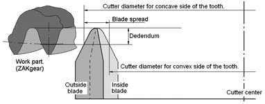
Geometry of ZAKGEAR spiral bevel production method. Click on image to enlarge:

The diameter of the cutter for ZAKgear is normally determined by the designer. However there are
guidelines to follow:
1.The smaller diameter is better for achieving better proportions of the top land if cut by
spread blade method.
2.The cutter has to be large enough in order to avoid interference when cutting the gear.
3.The diameter of the concave cutter for one member is always larger (3-10%) than the diameter
of the convex cutter for the other member.
It is done for localization of the contact patters.
Geometry of ZAKGEAR spiral bevel production method. Click on image to enlarge:

There is a practical reason for measuring ZAKGEAR cutters on the blade pitch points. Unlike the traditional spiral technology ZAKGEAR method allows calculation of the tooth geometry for the cutters with modified cutting edge including but not limited by Wildhaber-Novikov profile, root and tip relief, and tip and root radius. In general, the geometry of ZAKGEAR spiral bevel cutting blade is given by a list of x,y,z co-ordinates of the cutting edge points. While Direct Digital Simulation method determines the number of points [2n+1, n=1,2,3…], x,y,y co-ordinates can be, frankly, any realistic number.
| Other calculators: | ZAKGEAR roll and machine angle. | ZAKGEAR radial distance. Cradel angle. | Contact pattern. ZAKGEAR TCA |